
Taser Carleton Ltr Re M26 2000
Download original document:
Document text
Document text
This text is machine-read, and may contain errors. Check the original document to verify accuracy.
6, Carleton
~
Department of Electronics
5170 Mackenzie Building
1125 Colonel By Drive
Ottawa, Canada K1S 5B6
Tel: (613) 520-5754
Fax: (613) 520-5708
UNIVERSITY
14 February 2000
Stephen D. Tuttle
Director of Government & Law Enforcement Affairs
TASER International, Inc.
7339 E. Evans Road, Suite 1
Scottsdale
AZ 85260
USA
Re: ADVANCED T ASER® M26 Less Lethal System
Dear My. Tuttle,
I have reviewed the technical literature on the new ADVANCED TASER® M26 Less Lethal
System (see Document List below) and have reached the following conclusions.
(1) Consistency: The documents are, for the most part, technically consistent with each other.
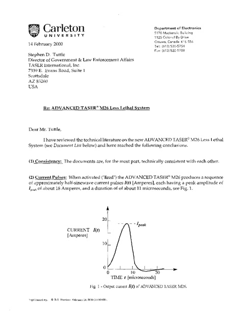
(2) Current Pulses: When activated ("fired") the ADVANCED TASER® M26 produces a sequence
of approximately half-sinewave current pulses I(t) [Amperes], each having a peak amplitude of
[peak of about 18 Amperes, and a duration of of about 11 microseconds, see Fig. 1.
20
~-lpea.
k
CURRENT let)
[A.mperes]
10
o::-" _ ~-'---.-_-:::----";;;:':::::;;;;;;~~_----"'''
o
10
20
TIME t [microseconds]
Fig I - Output current /(t) of ADVANCED TASER M26.
\rgh\t~5er'1.wp.
© R.O. J-h:m:'i8on
F~bruaI"Y
1'1, 2000 (11:3:::iA1\.1).
2
Each such current pulse flows from the TASER, along one of the deployed wires, through one of
the barbs into the skin of the victim, then back out through the other barb, along the other wire,
and finally back into the TASER. Note that there has to be a complete circuit for the current l(f)
to flow. Even if the barbs do not actually penetrate the skin, the current path can still be completed
if the the peak output voltage V peak appearing between the barbs is high enough to cause a spark
to jump the gap(s). This voltage can be estimated from Ohm's Law in the form
[VoltsJr
(1)
where R [Ohms] is the equivalent resistance of the subjects's tissue between the two barbs.
Assuming that R = 1,000 Ohms l , then the peak voltage will be 18 Volts x 1,000 Ohms = 18,000 Volts,
enough to jump a gap of about 1/4 inch in normal air, and more when the humidity is high. On
the other hand, the actual peak output voltage could be about 50,000 Volts before significant
current starts to flow, quickly decreasing thereafter. This means that an initial spark could jump
a gap of as much as 2/3 inch in normal air.
(3) Peak Power Output: The injection of each current pulse let) [Amperes] into the subject is
accompanied by a time-varying power pulse pet) [Watts], given by the equation
P(t) = I(tfxR
[Watts],
(2)
as shown in Fig. 2.
400,000
- -ppeali
INSTANTANEOUS
POWER P(t) [Watts]
200,000
o ~:Jlli:±iilli
o
10
20
TIME t [microseconds]
Fig. 2 - Instantaneous output power pet) of ADVi\J:'.JCED TASER M26.
Note that the numerical results obtained will be different if other values are asswned for R.
\rgh\taser4.wp,
© R.G. Hanison February 14, 2000 (11:20AM).
3
The peak power of each pulse is
(3)
or in this case, Pl'eak =(18 Amperesfx(l/OOO Ohms) = 324,000 Watts. This may look like a lot of
power, but it is only there for a very small fraction of the total firing time. The average power
PI/vemgc [Watts] is very much less/ and is calculated below in item (5).
Energy Per Pulse: The energy-per-pulse W Uoules] is given by the shaded area 2 under the
curve in Fig. 2. For the ADVANCED TASER® M26/ still assuming R = 1/000 Ohms, this area is
found to be
(4)
W
= 1.76 Joules-per-pulse.
(4)
This is four times the 0.44 Joules-per-pulse produced by the original AIR TASER ®34000.
(5) Average Power Output: While the ADVANCED TASER® M26 is actually being fired, the
pulses are delivered at a rate of
N
= 15 pulses-per-second.
(5)
Therefore the average power injected into the subject is only
Pavemge
= (W Joules-per-pulse)x(N pulses-per-second)
Uoules-per-second]
= [Watts],
that is,
PI/vemge
= 1.76 xIS = 26.4 Watts.
(6)
2
Mathematically, this area is given by the integral under the curve:
T
W
j'P(t) dt
o
[Watts} .
A simple way to find W is to divide the area into small squares of known area, and then multiply by the
number of squares.
\rgh\taser4.wp,
© RG. Harrison February 14,2000 111:20Al'\1) .
4
This is less than one ten-thousandth of the peak power Pp,ak' and is equivalent to about the power
used by an ordinary 25-Watt nO-volt lamp bulb. It is for this reason that the ADVANCED
TASER®M26 is properly described as a "26-Watt system".
(6) "Body Current": Several documents [1,3,8] show graphs of "Body Current" I rm , [Amperes]
versus Pulse Width [microseconds]. Inns is the the effective current that causes the average power
described in item (5). Because the pulse width (T = 11 microseconds) is only about 1/6000th of
the time between pulse peaks this current is very much less than the peak current discussed in
item (2). The "body current" Inns can be calculated from the average power PawTag, by means of the
equation
p
average
[Amperes rms] .
(7)
R
Using the appropriate numbers/ one finds for the ADVANCED TASER®M26 that
26.4 Watts
1000 Ohms
162.5
milli-Amperes rms.
This is similar to the value of 200 milli-Amperes shown on the "Electrical Output Safety
Measurement" charts t and agrees exactly with the result given by the formula 3 quoted there;
I rms
Jew [Joules])x(Repetition Rate
[Pulses/second)) / R[Ohms]
[Amperes rms].
(7) The ADVANCED TASER® M1S is similar to the M26 unit in all respects except for its pulse
rate, which is N = 10 pulses per second. The result is that although the energyW = 1.76 Joules-perpulse is the same as for the M26/ the average power is reduced to
P,11Jerage
= 1.76 xlO = 17.6 Watts,
(8)
or two-thirds of the average power produced by the ADVANCED TASER®M26. The MI8 unit is
3
In those documents the energy W [Joules} is written in the form E(J) and the [pulses/second]
are written in the form (Hz).
\rgh\taser4w~.
Ii)
R.G. Harrison February 14, 2DDD (112DAM).
5
thus properly described as an "lS-Watt systeITl".
Engineering: I have exaITlined key cOITlponents of the ADVANCED TASER® M26 and aITl
satisfied that it is manufactured according to good engineering principles. It should therefore be
reliable in use, provided that it is properly maintained. It might be susceptible to corrosion if
depleted batteries are left in place, so a rigid schedule of battery replacement should be enforced.
(8)
(9) In Summary, I can recommend the adoption of the ADVANCED TASER®M26 as a properly
engineered and useful alternative to more lethal ways of controlling violent subjects.
Yours sincerely,
Robert G. Harrison
Adjunct Research Professor
Document List
[1] "ADVANCED TASERM26 Medical Safety Information If, 22 pages, © 2000 Taser International, Inc.
[2] "ADVANCED TASER ELECTRICAL THEORY OF OPERATION", December 20, 1999.
[3] "100% TAKEDOWN POWER", brochure, © 1999 Taser International, Inc.
[4] "Certification Lesson Plan, AIR TASER® Model 34000 and ADVANCED TASER® M26", (includes
the CD-ROM "TASER® Files Version 4.0" ), Taser International, Inc.
[5] "Pulse Waveform Document", \attach \ Pulse Waveform. doc, 26 January 2000.
[6] "ADVANCED TASER M-SERIES EMD WEAPONS SPECIFICATIONS", in the CD-ROM
"TASER® Files Version 4.0".
[7] "The Voltage Myth", in CD-ROM "TASER@ Files Version 4.0".
[S} "ADVANCED TASER M-SERIES On-Line Owner's Manual", in the CD-ROM "TASER® Files
Version 4.0".
Note: The opinions expressed in this letter are entirely those of the author, and do not necessarily reflect
those of Carleton University.
\rgh\tascr4.wp,
© RG. Hanison February 14, 2000 (l1:20AM).
6
Notes about the Electrical Units quoted.
Current I describes the rate of flow of electrical charge along a conducting wire. Its units are
Amperes/ and it is analogous to the rate of flow of water in a hosepipe (units gallons/second),
Time-varying current I(t) refers to a varying rate of flow of electrical charge along a conducting
wire. Its units are Amperes/ and it is analogous to the varying rate of flow of water in a hosepipe
when the water pressure fluctuates.
Peak Current I peak (units Amperes) is the maximum value reached by a time-varying current.
The Voltage V appearing across a resistor R (units Ohms) is caused by the current I flowing
through it, according to Ohm/s Law V = IxR. Its units are Volts, and it is analogous to the
pressure difference appearing between the ends of a constricted hosepipe when water flows
through it (units pounds per square inch).
Peak voltage V peak (units Volts) is the maximum value reached by a time-varying voltage.
Energy W per pulse is a measure of the amount of "work" that each electrical pulse can do. Its
units are Joules/ and it is analogous to the "amount of work" that could be done by each glob of
water ejected from a pulsating lawn-watering hose.
The Power P dissipated in a resistor is a measure of the rate of transfer of energy into it. The power
heats the resistor up, and its units are Joules/second or equivalently/Watts.
Irgh\t.aser4.wp,
© RG. Harrison February 14, 2000 (1l:20AM).