
Taser X26 and Pacemakers Cleveland Clinic(2)
Download original document:
Document text
Document text
This text is machine-read, and may contain errors. Check the original document to verify accuracy.
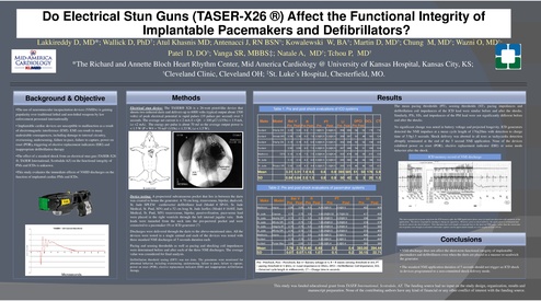
Do Electrical Stun
S
Guns
G
(TASER
(TASER( S -X26 ®)) Affect
ff
the Functional Integrity
g y off
I
Implantable
l t bl Pacemakers
P
k
and
d Defibrillators?
D fib ill t
?
Lakkireddy D,
D MD*; Wallick D
D, PhD†; Atul Khasnis MD; Antenacci J,
J RN BSN†; Kowalewski W,
W BA†; Martin D,
D MD†; Chung M,
M MD†; Wazni O,
O MD†;
Patel D
D, DO†; Vanga SR,
SR MBBS‡; Natale A,
A MD†; Tchou P,
P MD†
*The Richard and Annette Bloch Heart Rhythm Center
Center, Mid America Cardiology @ University of Kansas Hospital
Hospital, Kansas City
City, KS;
†Cleveland Clinic
Clinic, Cleveland OH; ‡St.
St Luke
Luke’ss Hospital,
Hospital Chesterfield,
Chesterfield MO
MO.
Background & Objective
•The use of neuromuscular incapacitation
p
devices ((NMIDs)) is ggaining
g
popularity over traditional lethal and non-lethal weapons by law
enforcement personnel internationally
• Implantable cardiac devices are susceptible to malfunction as a result
of electromagnetic
g
interference (EMI).
(
) EMI can result in many
y
undesirable consequences, including damage to internal circuitry,
oversensing, undersensing, failure to pace, failure to capture, power on
reset (POR), triggering of elective replacement indicators (ERI) and
inappropriate defibrillation therapy

Results
R
l

Methods
Electrical stun device: The TASER® X26 is a 26-watt pistol-like device that
shoots
two tethered
andd delivers
up to 6000 volts
1500
h
h d darts
d
d li
l (typical
( i l output about
b
volts) of peak electrical potential in rapid pulses (19 pulses per second) over 5
seconds. The average
g net current is < 2 mA ((I = Q
Q/t = 100 µ
µC/ ((1/19s)) = 1.9 mA,,
i.e <2 mA). The energy per pulse is about 70 mJ so the average output power is
< 1.5 W (P = W/t = 70 mJ/ (1/19s) = 1.33 W, i.e < 1.5 W).

Table 1: Pre and post shock evaluations of ICD systems

Make

Model

R

PT

Pre Post Pre Post

Pre

DFCI DCL

LI

CT

Pre Post Pre Post

Post

Guidant

Vitality DS

3.20

3.20

9.3

7.1 1.4@0.5

0.4@0.5

394

369

54

52

178

7.6

Guidant

Ventak MS

2.58

2.58

8.0

7.8 0.2@0.5
@
0.2@0.5
@

389

397

50

49

160

5.4

Guidant

Vitality DS

3 19
3.19

3 19
3.19

80
8.0

6 9 0.2@0.5
6.9
0 2@0 5 0.2@0.5
0 2@0 5

352

354

50

52

154

49
4.9

2 93
2.93

2 93
2.93

80
8.0

7 0 0.2@0.5
7.0
0 2@0 5 0.2@0.5
0 2@0 5

367

348

54

51

169

84
8.4

5.16

5.16

7.5

7.5 2.0@0.4 2.0@0.4

500

474

59

59

210

5.6

3.10

3.10

4.2

4.9 0.2@0.5 2.2@0.5

395

380

44

44

196

5.2

3.00

3.00

4.3

4.4 0.2@0.5 1.0@0.5

355

375

46

46

165

4.3

Guidant
Medtronic

•The effect of a standard shock from an electrical stun gun (TASER-X26
®, TASER International, Scottsdale AZ) on the functional integrity of
PMs and ICDs is unknown.

Bat V

7273

(PT) sensing thresholds (ST),
(ST) pacing impedances and
The mean pacing thresholds (PT),
defibrillation coil impedances of the ICD lead were similar before and after the shocks.
shocks
Similarly, PTs, STs, and impedances of the PM lead were not significantly different before
and after the shocks.
No significant change was noted in battery voltage and projected longevity.
longevity ICD generators
detected the NMI impulses at a mean cycle length of 176+20ms with detection to charge
time of 5.9
5.9+1.5
1.5 seconds. Shock delivery was aborted in all tests as tachycardia detection
abruptly
p y terminated at the end of the 5 second NMI application.
pp
None of the devices
exhibited power on reset (POR), elective replacement indicator (ERI) or noise mode
behavior after the shock.
ICD memoryy record of NMI discharge
g

St. Jude
St. Jude

•This study
y evaluates the immediate effects of NMID discharges
g on the
function of implanted cardiac PMs and ICDs.

Photon VR

Mean

3.31 3.31 7.0 6.5

0.6

0.9 393 385 51

SD

0.84 0.84 2.0 1.3

0.8

0.9

50 42

5

50 176 5.9
5

20 1.5

Table 2: Pre and post shock evaluations of pacemaker systems
Device testing: A prepectoral subcutaneous pocket that lies in between the darts
was created to house the generator.
generator A 70 cm long,
long transvenous,
transvenous bipolar,
bipolar dual-coil,
dual coil
St. Jude SPLTM cardioverter defibrillator lead (Model # SP
SP-01,
01, St. Jude
Medical, St. Paul, MN) and a 52 cm long St. Jude Isoflex (Model # 1648T, Jude
Medical, St. Paul, MN) transvenous, bipolar, passive-fixation, pace-sense lead
were placed
l d in
i the
h right
i h ventricle
i l through
h
h the
h left
l f internal
i
l jugular
j
l vein.
i
B h
Both
leads were tunneled from the neck into the pre-pectoral
pre pectoral pocket and were
connected to a ppacemaker ((9)) or ICD ggenerator ((7))
Discharges were delivered through the darts to the above-mentioned sites
sites. All the
g animal and each of the devices was tested with
devices were tested in a single
three standard NMI discharges of 5 seconds duration each.
g and sensing
g thresholds as well as ppacing
g and shocking
g coil impedances
p
Pacing
were determined before and after each of the three NMI discharges. The average
value was considered for final analysis.
Defibrillation threshold testing (DFT) was not done. The generators were monitored for
abnormal behavior,
behavior including oversensing,
oversensing undersensing,
undersensing failure to pace,
pace failure to capture,
capture
power on reset ((POR),
p
) elective replacement
p
indicator ((ERI)) and inappropriate
pp p
defibrillation
therapy.

Make

Model

Bat V
R
Pre Post Pre Post

PT
Pre

LI
Post

Pre

Post

Medtronic

Insync

2.95

2.95

8.0

8.0 0.5@0.5

0.5@0.5

422

409

St. Jude

Enpulse

2.75

2.75

5.6

5.6 0.25@0.52

0.75@0.52

417

423

St. Jude

Identity DR

2.73

2.71

5.0

5.3 0.25@0.5

0.25@0.5

334

356

St. Jude

Affinity DR

2.75

2.75

7.0

7.0 0.25@0.8

0.25@0.8

374

374

St Jude
St.

Integrity AF

2 75
2.75

2 76
2.76

62
6.2

6 4 0.25@0.4
6.4
0 25@0 4

0 25@0 4
0.25@0.4

401

383

St. Jude

Affinityy DR

2.76

2.76

7.0

7.0 0.25@0.5
@

0.25@0.5
@

373

403

Medtronic

Insync

2.77

2.77

8.0

8.0 0.5@0.5

0.5@0.5

426

422

2.78

2.76

5.7

5.3 0.3@0.5

0.3@0.5

410

400

2.86

2.85

5.1

5.8 0.2@0.4

0.3@0.4

380

380

Guidant
Guidant

Mean
SD

Pulsar Max

2.79
2 79
0 07
0.07

2.78
2
78 6.40
6 40
0 07 1.15
0.07
1 15

6.48
6 48
1 07
1.07

0.3
03
01
0.1

0.4
0
4
02
0.2

393.00
393
00 394.44
394 44
30 15
30.15
22 71
22.71

Pre ‐ Preshock, Post
Pre
Preshock, Post ‐ Postshock, Bat V
Postshock, Bat V– Battery voltage in V, R
Battery voltage in V, R – R waves sensing threshold in mV, PT
R waves sensing threshold in mV, PT
– pacing threshold in V @ms, LI –Lead impedance in Ohms, DFCI – Defibrillation Coil Impedance, DCL
– Detected cycle length in milliseconds, CT – Charge time in seconds.

This interrogated electrogram strip from the ICD memory after the NMI application shows onset of rapid rate detection with initiation of the
application.
l
Th
The ddevice responds
d bby starting to charge
h
its capacitors. However,
H
prior to shock
h k delivery,
d l
the
h application
l
is terminated
d and
d
the device aborts the shock delivery. Note that detected cycle length corresponds best to the detected NMI pulses rather than the ventricular
electrograms
l
even though
h
h accelerated
l
d ventricular
i l capture can bbe appreciated
i d visually
i ll at cycle
l llengths
h around
d 240 ms.

Conclusions
C
l i
• NMI discharge does not affect the short-term functional integrity of implantable
pacemakers and defibrillators even when the darts are placed in a manner to sandwich
th generator.
the
t
• The standard NMI application
pp
duration of 5 seconds should not trigger
gg an ICD shock
in devices programmed to a non-committed shock delivery mode.

This study was funded educational grant from TASER International, Scottsdale, AZ. The funding source had no input on the study design, organization, results and
manuscript
i t preparation.
ti
N
None off th
the contributing
t ib ti authors
th hhave any kind
ki d off financial
fi
i l or any other
th conflict
fli t off iinterest
t
t with
ith th
the ffunding
di source.